EN
EN  DE
DE  RU
RU  PT
PT  JA
JA  ES
ES  IT
IT Machine Perimeter Guarding | Industrial Automation Safety
20x100mm Mesh for Compact Robot Cell Guarding Without Sacrificing Safety Distance
For large automated equipment, the choice between 50x50mm wire mesh and a 20x100mm machine guarding fence can determine whether a project loses valuable forklift clearance or preserves usable factory floor. This engineering approach uses narrow-aperture framed mesh panels to support a risk-assessed 120mm guarding position—subject to the applicable ISO/GB calculation and the final project configuration.
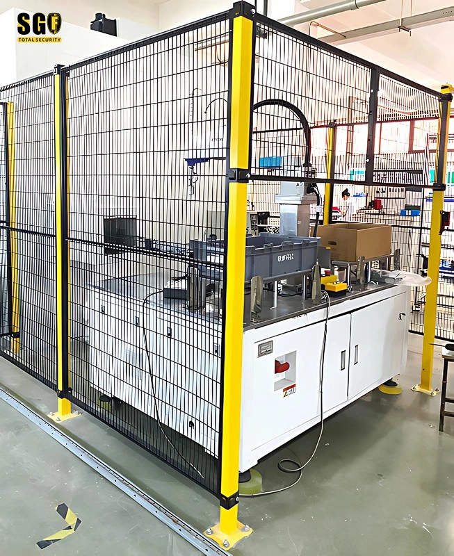
Why Large Automation Cells Lose Valuable Floor Space
A large robot, palletizer, conveyor, or CNC cell needs a physical guarding boundary—not just a visible line. With a common 50x50mm mesh, the required reach-through safety distance can push the fence back from the hazard. In the GBIM scenario, the reference distance is 850mm. That setback can narrow forklift and pedestrian routes, reduce production area, and make an already large automation system harder to integrate. The correct comparison is therefore not only panel price. It is the usable footprint of the complete robot safety fencing system.
| Engineering point | Design implication |
|---|---|
| 50x50mm conventional mesh | May require a larger reach-through setback; the GBIM reference is 850mm and must be checked against the applicable safety-distance table. |
| 20x100mm narrow-aperture mesh | Can support a much closer guarding position; the GBIM reference is 120mm, subject to hazard geometry, risk assessment and applicable ISO/GB requirements. |
| Factory traffic interface | Keep forklift and pedestrian clearance in the layout instead of treating the safety fence as an afterthought. |
| Project approval | Confirm the final mesh, hazard height, opening, gate, interlock and anchoring details before claiming compliance. |
How the Framed Mesh System Fits a Tighter Safety Boundary
Narrow mesh changes the layout calculation
The 20x100mm opening is the key product adaptation for this space-constrained machine guarding fence application. Compared with the proposed 50x50mm alternative, its narrow dimension limits reach-through exposure in the relevant direction. For GBIM, this creates the engineering basis for positioning the guarding line at the stated 120mm reference rather than the 850mm reference associated with the old layout. It is not a universal clearance promise: the integrator must verify ISO 13857/ISO 14120 or the locally applicable standard against the actual robot envelope and access points.
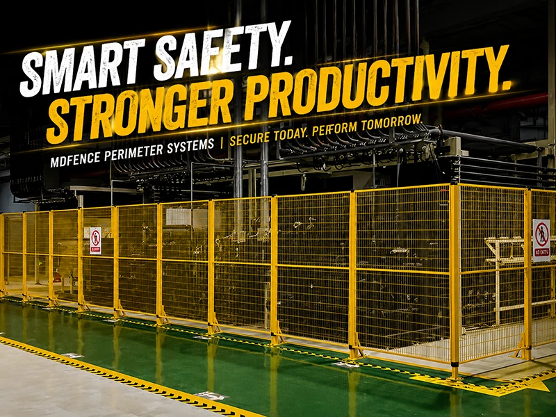
Rigid panels, posts and anchored joints make the boundary repeatable
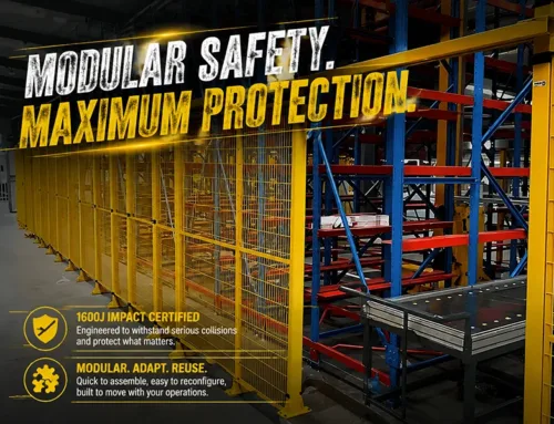
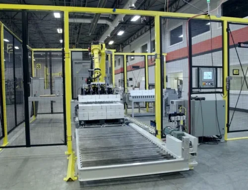
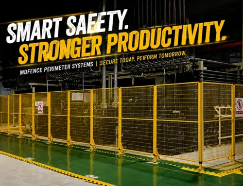
This is a framed, modular industrial safety fence rather than a loose roll of wire. Typical Mdfence construction uses Q235 carbon steel, welded framed mesh panels, steel safety fence posts, fixing rings and bolted base plates. The installation evidence shows continuous perimeter guarding, floor-mounted posts and panel-to-post connections around production equipment. Standard configurations commonly use 3.0mm or 4.0mm wire, 40x60mm or 60x60mm posts, and M10 expansion anchors; the project drawing and floor condition govern the final selection.
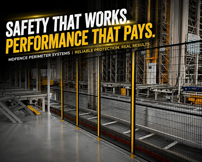
Impact and access details stay visible in the specification
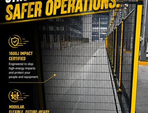
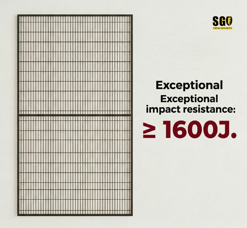
For an automation cell beside factory traffic, the panel is only one part of the physical guarding solution. The documented standard system includes a ≥1600J impact reference, reinforced framed construction, powder-coated steel, and access modules that can accept safety lock mounting carriers. Omron D4NL or Pizzato FS series devices can be provided with a suitable mounting interface; the safety switch, PLC and stop circuit remain project responsibilities. This keeps the machine safety fence aligned with gate access, LOTO and industrial automation safety rather than treating the mesh as a standalone product.
What the Compact Layout Delivers to the End Customer
- More usable floor area: a closer, risk-assessed guarding line can return space to forklift and pedestrian circulation.
- Smaller automation footprints: integrators can offer compact robot cell guarding around robots, conveyors and control cabinets.
- Clearer equipment isolation: framed mesh panels, anchored posts and controlled gates create a defined machine perimeter guarding zone.
- Lower redesign exposure: modular panels can be removed, extended or reconfigured when the production line changes, unlike welded safety fencing that usually requires cutting and rework.
- Better project evidence: the BOM can identify mesh aperture, wire diameter, post section, gate type, safety interlock interface and anchoring method for review.
For GBIM, the commercial benefit is not limited to saving steel. A compact, standards-reviewed industrial safety fencing layout can allow the delivered automation cell to occupy fewer square metres of expensive customer factory space. That footprint advantage can become a tangible differentiator when every aisle, service zone and production bay has already been allocated.
Specify the Boundary Before You Specify the Fence
Start with the robot motion envelope, hazard height, reach-through direction, required access, forklift route and floor condition. Then confirm whether 20x100mm wire mesh panels, the selected post section, gate hardware, Omron D4NL or Pizzato FS series carrier, and the anchoring package meet the project calculation. The 120mm and 850mm values in this article are GBIM layout references—not substitutes for a documented risk assessment or local regulatory review.
Plan a Machine Guarding Fence Around the Real Hazard Envelope
Send the robot-cell drawing, hazard dimensions, traffic clearances and gate requirements. We can map a configurable safety fence layout with the appropriate mesh, posts, access and fixing details for engineering review.