EN
 DE
 RU
 PT
 JA
 ES
 IT
FENCE ANCHORAGE / IMPACT LOAD PATH / CONCRETE SLAB
A panel can pass every thickness check and still leave the floor on the first real hit
EHS teams and plant engineers often sign off a guarding quotation on mesh thickness alone. When a 100 kg load travelling at 20 km/h reaches the fence, the force does not stop at the wire: it runs through the weld points, the 20x30x1.5 mm frame, the clamp rings, the 60×60 mm post working as a cantilever, the 140x140x5 mm base plate and four M10 expansion bolts before it reaches the concrete. If any one of those links is missing, the post is pulled out and the whole run is wasted. Fence anchorage expansion bolt selection is therefore the last step of an impact load path calculation, not a hardware afterthought.
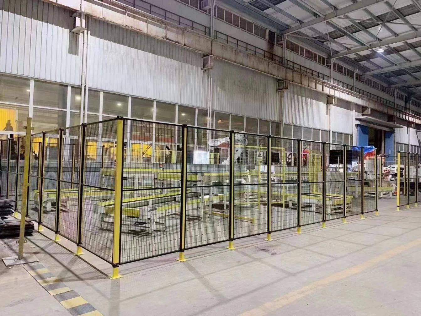
The eight links between the wire and the ground
An impact is a chain, not a component. Overturning moment at panel height becomes tension in the bolts on the far side of the base plate and shear across all four. The check that matters is therefore the pull-out capacity of the anchor against the slab, not the gauge of the mesh.
| Load path link | What it has to carry |
|---|---|
| Mesh face, 3.0 or 4.0 mm wire | Transfers the contact force into the weld points without tearing. |
| Weld points and 20x30x1.5 mm tube border | Spreads a point load into the panel frame; flat full welds keep the load in shear rather than peel. |
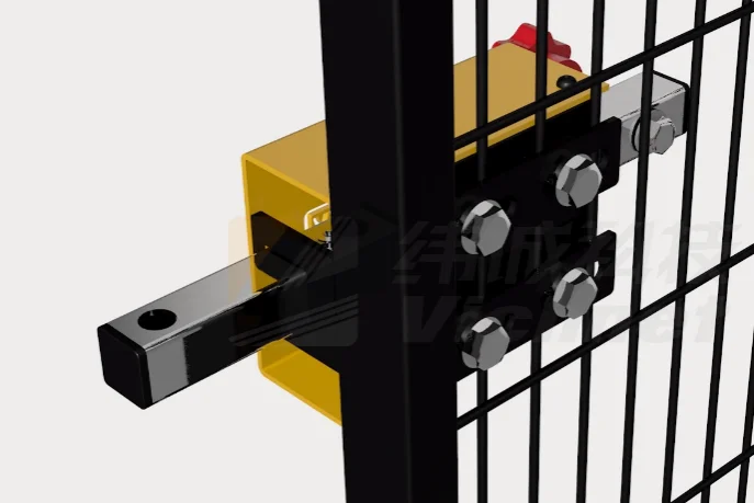
| Clamp rings with M8 fasteners | Passes frame load into the post without drilling the post on site. |
| 60x60x2.0 mm Q235 post | Works as a cantilever; bending moment peaks at the base plate. |
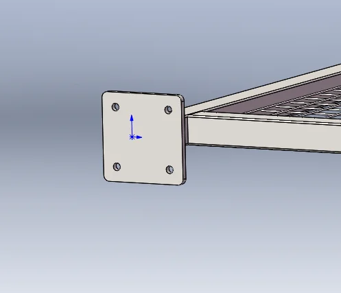
| 140x140x5 mm welded base plate | Converts that moment into bolt tension and bolt shear. |
| Four M10x70 or M10x80 expansion bolts | Resist pull-out and shear in the concrete. |
| Concrete slab | Must provide the strength, thickness and edge distance the bolt data sheet assumes. |
Three checks that belong before the order, not after the impact
Turn moment into tension and shear
Take the documented figure of at least 1600 J for the standard system as an input, not a blanket promise. A load applied near the top of a 2000 mm panel produces an overturning moment at the foot; with a 140 mm base plate the lever arm inside the bolt group is small, so the far-side bolts see most of the tension while all four see shear. Ask for the anchor calculation with the bolt group geometry and the assumed concrete class. The figure in the project specification applies to the standard configuration; customised sizes are excluded and need their own verification.
Verify the slab before you choose the bolt
Concrete strength class, slab thickness, embedment depth and distance to a free edge or a joint decide whether M10x70 or M10x80 is appropriate. A post set too close to a saw cut will fail by concrete breakout long before the bolt yields. Cores, rebar scans and a pull-out test on a representative position are cheap compared with re-drilling a line of posts. Where the slab cannot be verified, a through-bolted or cast-in solution has to be engineered by the project team rather than assumed from a catalogue.
Why site welding is not a repair
Adding a bead on site to stiffen a post burns through the epoxy-polyester powder coating and leaves an untreated heat-affected zone. It also changes the load path the anchor calculation was written for, so the acceptance evidence no longer matches the installed system. Prefabricated clamp rings keep the 60×60 post intact, keep the corrosion layer intact and keep the bolted chain inspectable. If a layout needs more restraint, the fix is a different post spacing or base plate specification, drawn and supplied before installation.
Where this check changes the specification
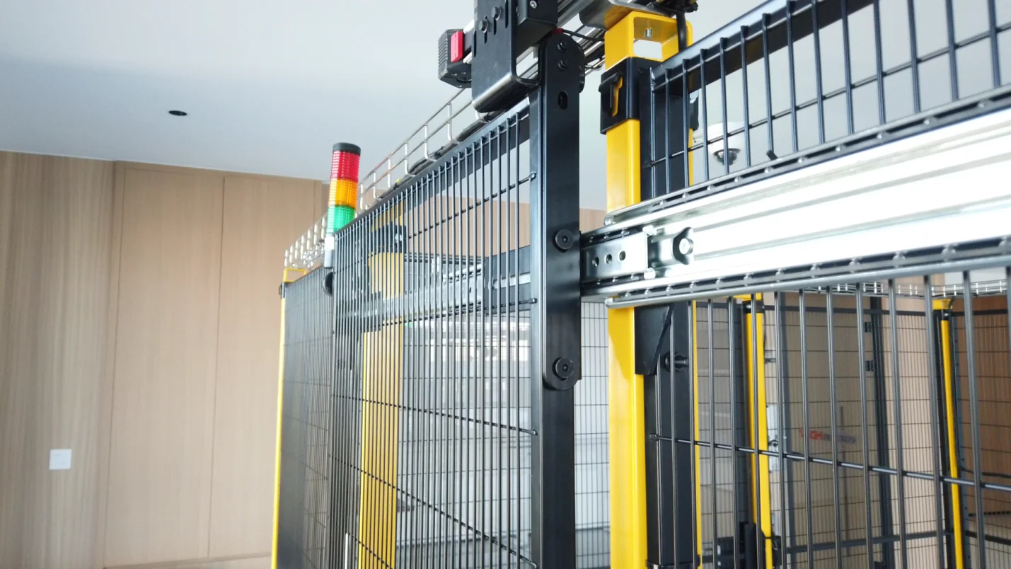
- Robot cells and palletisers where a loaded fixture can strike the fence above mid height.
- Forklift and AGV aisles where the post line sits close to a slab joint or a floor drain.
- CNC and press enclosures on mezzanines or thin toppings where embedment depth is limited.
- Lines planned for future relocation, where anchor positions need to be recoverable rather than grouted in.
- Projects with EHS acceptance sign-off that requires the anchor calculation as part of the handover file.
In each case the drawing set should state the fence anchorage expansion bolt size, the embedment, the concrete class and the assumed impact case. That is what lets an EHS reviewer follow the impact load path from the mesh to the slab without a site visit.
What to put in the enquiry
Send the slab thickness and strength class, joint and edge locations, panel height, post spacing and the impact case from your risk assessment. The return should be a bolt schedule, a base plate detail and the anchorage calculation sheet tied to the panel layout, so the mechanical chain and the civil substrate are checked as one system.
Have the anchorage checked before the line is drilled
A guarding run is only as strong as its last connection. Share the floor data and we will map the impact load path against the standard configuration and flag the positions that need a different anchor.