EN
EN  DE
DE  RU
RU  PT
PT  JA
JA  ES
ES  IT
IT Robot Cell Guarding
Robot Cell Maintenance Access with Mdfence Gates and Mesh Panels
Mdfence is a configurable steel machine-guarding system for robot cells, automation equipment, conveyors, and controlled maintenance access. This guide explains how framed mesh panels, access gates, support wheels, fixing rings, and anchored posts should be coordinated with the machine layout and the integrator’s safety interfaces.
Project parameters to confirm before fabrication
Maintenance access is a layout issue, not only a gate-selection issue. Confirm the robot envelope, service path, gate opening, panel arrangement, floor condition, and safety-switch interface before the Mdfence configuration is released. The following values are documented options or common project parameters, not automatic specifications for every installation.
| Item | Documented option or project condition |
|---|---|
| Product scope | Configurable Mdfence machine guarding for robot cells, automation equipment, conveyors, and controlled access areas. |
| Framed mesh | A 20 x 30 x 1.5 mm tubular mesh-panel frame is a documented option; confirm the final frame specification for the project. |
| Steel material | Q235 carbon steel is a documented material option; confirm the material and coating specification in the project documents. |
| Mesh opening | 20 x 100 mm is a documented common configuration; select the opening after reviewing the hazard, access points, and applicable safety-distance calculations. |
| Posts | Common post sections include 40 x 60 mm and 60 x 60 mm square tube; the final section and height require project confirmation. |
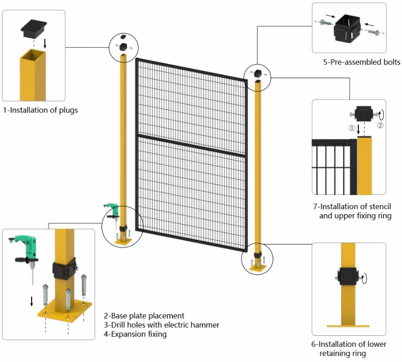
| Panel connection | Mesh panels may use fixing rings or clamps with M8 fasteners to support assembly, removal, and layout changes. |
| Floor anchoring | Posts are commonly fixed through base plates using project-confirmed M10 x 70 mm, M10 x 80 mm, or M8 expansion anchors on suitable concrete floors. |
| Safety interface | Mounting carriers can be prepared for devices such as Omron D4NL or Pizzato FS series switches; the switch, PLC, and complete safety-control circuit remain project responsibilities. |
Four interfaces that shape maintenance access
Start with the robot-cell access route
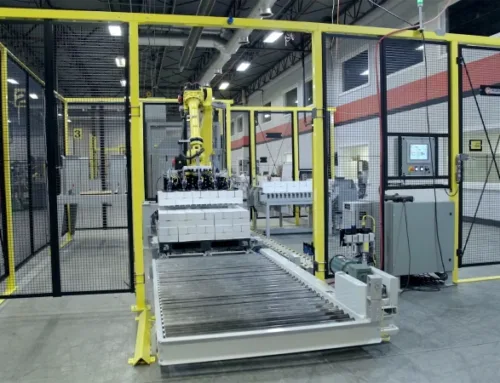
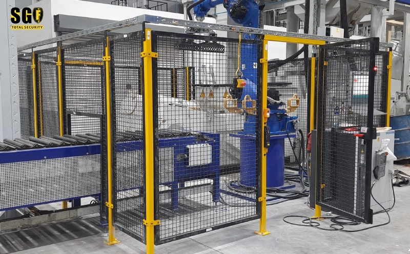
The robot-cell overview shows the guarding boundary, access gate, and equipment zone as one layout. Place the maintenance opening where technicians can reach service points without creating an uncontrolled path into the cell. Confirm the gate swing, adjacent equipment, conveyor clearance, and required opening with the machine integrator before finalizing the panel arrangement.
Use framed mesh panels where removal matters
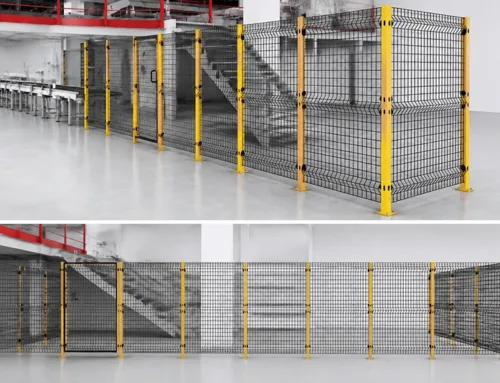
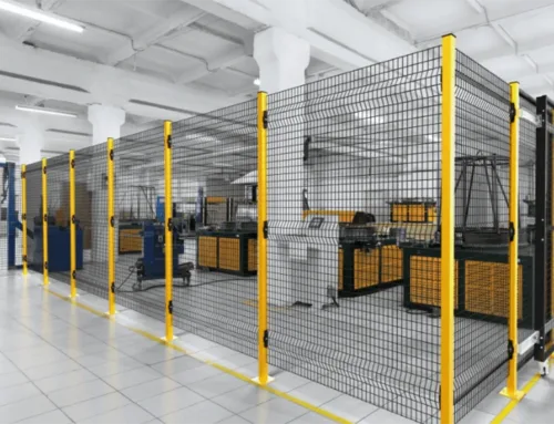
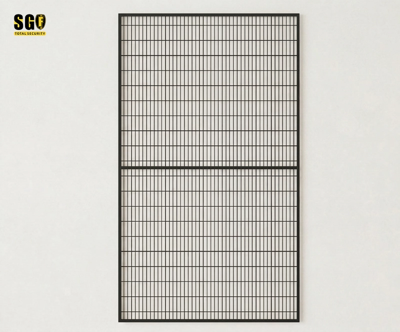
The framed panel arrangement uses a steel perimeter and welded mesh infill. Fixing rings or screws allow a panel to be removed or repositioned without cutting the surrounding guard. A documented 20 x 30 x 1.5 mm frame option and 20 x 100 mm mesh configuration may be considered, but both require confirmation against the project risk assessment and approved drawing.
Support the gate and coordinate the safety interface
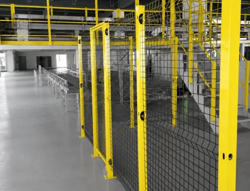
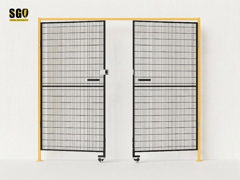
A wide or frequently used access gate may need support wheels or caster supports to help maintain its operating position. The double-swing gate example shows the gate leaves, latch area, and support components as a mechanical assembly. If a safety switch is used, its mounting position and actuator alignment must be coordinated with the gate design. Mdfence provides the physical mounting interface; the integrator defines the safety logic and control response.
Where this layout approach applies
- Robot cell guarding for six-axis robots, control cabinets, conveyors, and service zones.
- Maintenance-access gates for automation cells where panels may need to be removed or rearranged during equipment changes.
- Conveyor and material-transfer boundaries where the opening geometry must be coordinated with the machine layout and access restrictions.
- Flexible manufacturing areas that require modular panels, anchored posts, and project-specific gate arrangements.
- Factory equipment enclosures where floor condition, anchor selection, and safety-switch mounting must be reviewed together.
The practical design question is whether the maintenance route, gate hardware, removable panel connections, and safety interface work as one approved arrangement. Mdfence supports that coordination, but final dimensions, anchoring, gate support, and control behavior must be confirmed for the specific cell.
Request the project drawing and interface details
Use the project documentation request to confirm the robot-cell layout, gate opening, panel schedule, post sections, fixing-ring positions, floor anchors, and safety-switch mounting carrier. Provide the machine layout and service-access requirements so the Mdfence arrangement can be reviewed before fabrication.
Plan maintenance access before the cell is built
Send your robot-cell layout, service opening requirements, floor information, and preferred safety-switch interface to the Mdfence engineering team. We can review the framed mesh arrangement, gate support requirements, post connections, and project responsibilities with your integrator. Contact us at /contact-us/.