EN
EN  DE
DE  RU
RU  PT
PT  JA
JA  ES
ES  IT
IT Machine Guarding Systems
Machine Guarding Systems for Plasma-Cutting Debris Control and Floor-Space Recovery
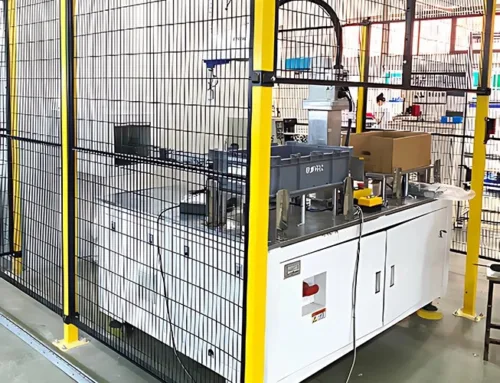
When plasma cutting and milling throw metal chips at high speed, the fence has to stop debris and sit close to the machine. Mdfence solves both with a 20×100 mm anti-reach mesh and a rigid 20×30 mm fully welded rectangular frame, allowing legal installation as close as 120 mm under ISO-aligned guarding practice.
Why plasma-cutting cells create a space problem
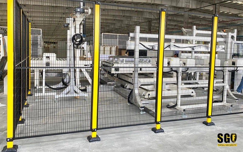
A large plasma cutter or milling center does not just need a barrier. It throws high-speed metal swarf, and that changes the whole layout. If the mesh aperture is too open, the fence must be pushed far back to meet safety intent. The result is predictable: wide no-go bands, lost aisle width, and expensive factory floor that cannot be used for storage, movement, or future equipment.
| Specification | Why it matters |
|---|---|
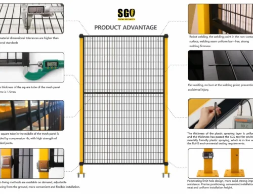
| 20×100 mm anti-reach mesh | Blocks direct finger access and helps contain flying metal chips without forcing a loose perimeter. |
| 20×30 mm fully welded rectangular frame | Delivers high bending stiffness so the fence stays rigid in tight machine-cell installations. |
| Legal close-in installation to 120 mm | Helps reclaim usable floor space while keeping the guarding line close to the hazard zone. |
| ISO-aligned machine guarding layout | Supports a practical safety position that balances containment, access control, and space efficiency. |
Why Mdfence fits this application
1. Narrow-aperture mesh that stops the right kind of hazard
The 20×100 mm narrow opening is not a generic fence pattern. It is selected for machine guarding where the main issue is fast, sharp debris and the risk of reach-in contact. Around plasma cutting and milling equipment, that geometry gives the cell a tighter defensive envelope without turning the whole floor into dead space.
2. A welded frame that supports close mounting
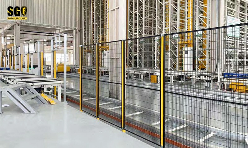
Close mounting only works when the frame is stiff enough to stay true. The 20×30 mm fully welded rectangular tube gives the panel the rigidity needed for compact layouts, so the fence can be set close to the machine without the weak, flexible feel that often appears in lighter guarding systems. That stiffness is what makes the 120 mm setback practical rather than theoretical.
3. Layout evidence from the installed cell
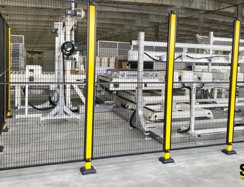
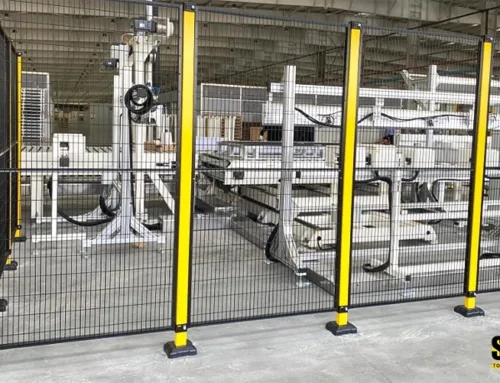
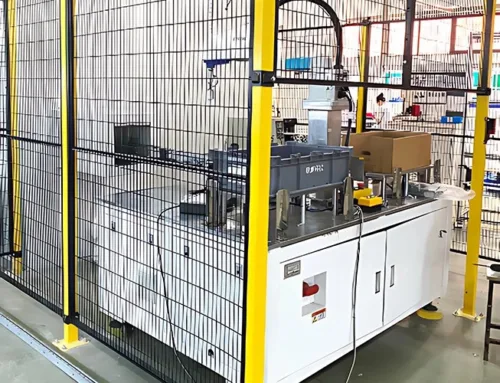
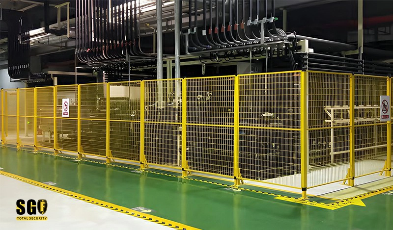
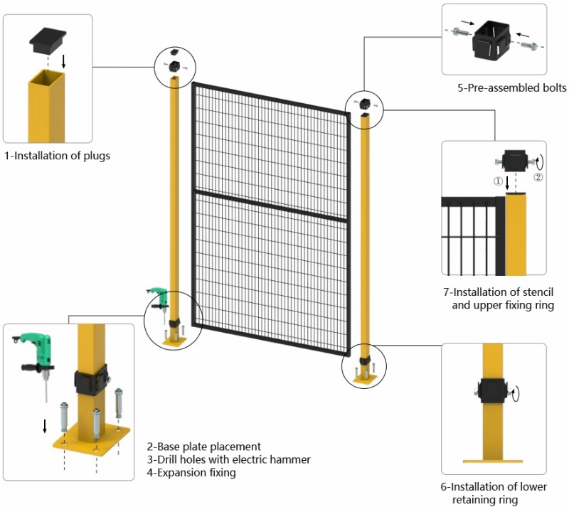
The installation image shows how the base plate, drilling pattern, and retaining hardware come together as a repeatable system. The factory-wide view matters because it proves the fence is not only a component choice; it is a space strategy. The machine line stays protected, the aisle stays usable, and the protected perimeter no longer steals the whole room.
Where this guarding approach is used
- Plasma-cutting cells that throw fine, fast metal fragments.
- Milling and machining areas where chips travel outside the machine envelope.
- Retrofits in plants that need to recover aisle width without rebuilding the whole line.
- Mixed production floors where the guarding line must stay compact and serviceable.
For each of these layouts, the value is the same: the guard stays close enough to protect, stiff enough to hold position, and compact enough to return expensive floor area to productive use.
What to ask for before you specify the fence
Ask for the aperture size, frame section, installation setback, and the exact machine hazard being controlled. For plasma-cutting and milling environments, Mdfence is built around those variables from the start, so the answer is not a generic barrier but a guarding layout that fits the real debris pattern and the real floor plan.
Need to reclaim floor space around a cutting cell?
Send the machine footprint and the aisle width you want to preserve. We will map the guarding line, check the setback, and show how a 20×100 mm narrow-aperture system with a 20×30 mm welded frame can solve the debris-control problem without wasting the room.