EN
 DE
 RU
 PT
 JA
 ES
 IT

01Two Columns, One Purpose
Most site rework on a guarding project traces back to a parameter nobody wrote down. A response sheet puts the client’s requirement and the supplier’s answer side by side, line by line, while the layout is still on paper. In one equipment-guarding proposal the sheet ran to eight client-specified lines, eight responses and three optional items.
02What the Client Fixed
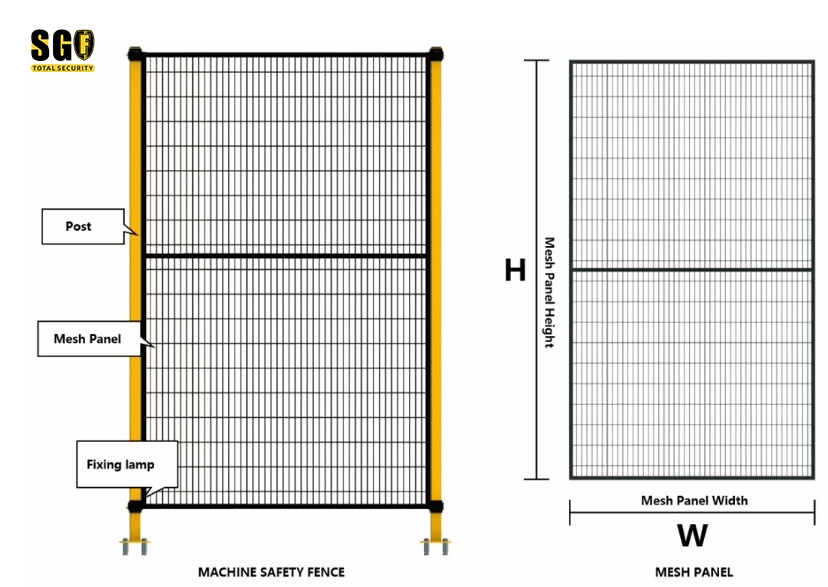
- Post section: 40 x 60 mm.
- Height: mesh panel 180 mm off the floor, top height adjustable around 2200 mm.
- Mesh opening: 20 x 100 mm.
- Wire diameter: 3.0 mm.
- Gate: hinged, with a connecting cross beam that stiffens the gate in the open position.
- Locks and electrical safety switches: supplied and installed by a party appointed by the client; the fence supplier does not provide them.
- Quantity: approximately 500 m, with the number of gates not yet fixed.
- Installation: mesh panels may be cut to fit on site.
03What We Confirmed Back
- 40 x 60 mm post: confirmed.
- 180 mm floor gap with 2200 mm post: confirmed. Raising the mesh panel to sit flush with the post top is possible but marked to be confirmed, not assumed.
- 20 x 100 mm opening and 3.0 mm wire: confirmed.
- Hinged gate with cross beam: confirmed, including its stiffening function.
- Client-supplied switch: the supplier requires the switch’s mounting parameters in order to design a custom latch carrier.
- 500 m: gate and fitting quantities remain open.
- On-site cutting: spare parts to be provisioned against an estimated adjustment quantity.
The discipline here is that to be confirmed is written down rather than filled in. A guessed value in a response sheet becomes a wrong hole pattern or a missing gate three months later.

04The Safety Interlock Interface Belongs in the Design Pack
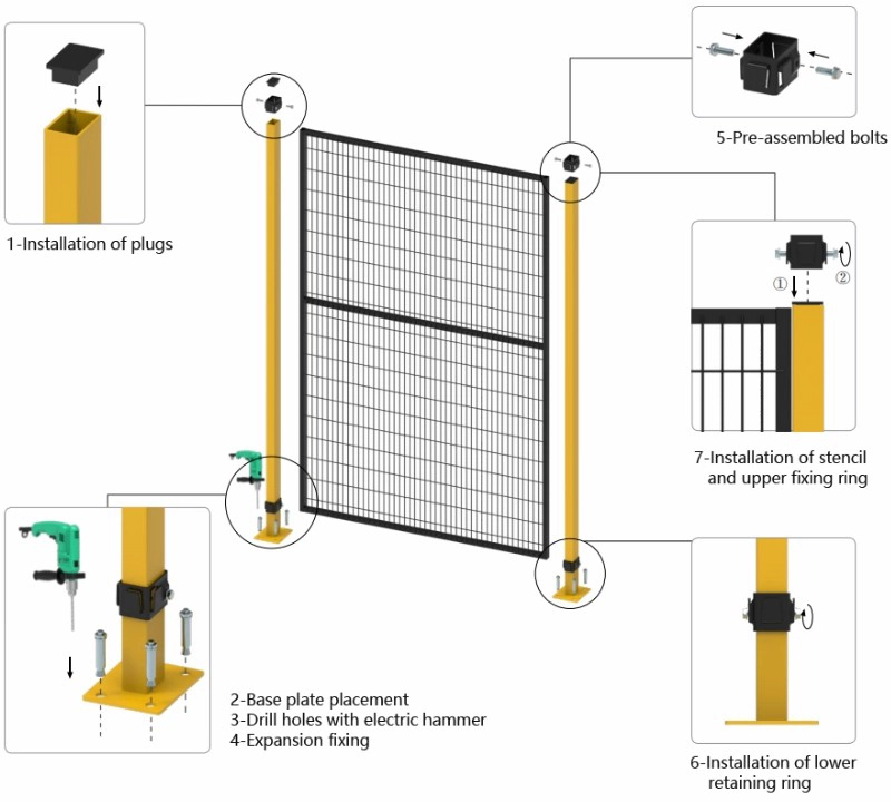
The single line that most often holds up an integrator’s design pack is the safety switch. When the client names a switch such as an Omron D4NL and supplies it separately, the fence supplier cannot simply drill a hole in a finished post. Drilling on site breaks the powder coating, leaves bare steel at the fixing point, and produces a mounting face that no longer matches the switch’s key alignment. An adaptive lock carrier is the engineered answer: a pre-designed mounting plate and latch carrier that accepts the specified switch hole pattern and keeps the gate in the machine safety circuit.
To draw that carrier into the layout, the design pack needs four things from the integrator:
- The exact switch model and its mounting dimensions, so the plate hole pattern is fixed before release.
- The gate type and handing, since a hinged safety gate and a sliding safety gate put the actuator in different positions.
- The approach direction and any adjacent panel or cross beam that could foul the actuator.
- Confirmation of who supplies and installs the switch, recorded as an exclusion in the proposal rather than left implicit.
With those four lines settled, the carrier becomes a drawing item instead of a site modification. The same response sheet also carries the items nobody asked for but the site will need: plastic or all-metal handles, support castor kits for wide gates, black plastic post end caps and two-piece base covers, and cut-edge protection for trimmed mesh — either a rubber strip over a stainless-steel core or a slotted angle trim.
05Three Handovers From the Same Sheet
- For the designer: lock the confirmed lines into the CAD layout and leave explicit placeholders for the open ones. Do not draw a flush panel top or a switch mounting hole until those lines are confirmed.
- For the project manager: build the procurement list from confirmed quantities and hold a spare-parts allowance against the cutting estimate and the unconfirmed gate count.
- For the sales manager: carry the open lines into the quotation as stated assumptions, so a later change is a variation rather than a dispute.
06Scope Note
The parameters above describe one project and one proposal revision. The 20 x 100 mm opening is often associated with a shorter safety distance under ISO 13857, but the required distance depends on the hazard and the reach path in that specific cell; it cannot be carried over from this sheet as a general claim. Material call-outs also differ between the source proposals — one names Q195 for the posts and another Q235 — so the released engineering drawing, not this document, governs the grade. Switch model names are used here to describe an interface requirement, not to specify a supplied component.
Is the safety switch client-supplied?
Send the switch model, gate type and handing so the carrier becomes a drawing item instead of a site modification.