JA
 EN
 DE
 RU
 PT
 ES
 IT
ISO 13857 safety distance · machine guarding fence
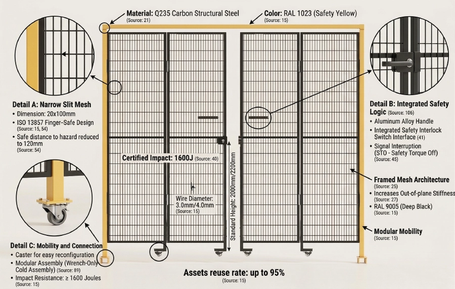
Where the fence line actually goes: a 20 x 100 mm mesh and the 120 mm offset it supports
EHS reviews stall on one question: how far must the industrial safety fencing sit from the hazard? For a 20 x 100 mm finger safe mesh, the reach-through table in ISO 13857 returns a 120 mm safety distance. That number is derived from the opening, not chosen on site — and it is a floor, not a universal offset. Here is the derivation order, and the point where 120 mm stops applying.
Most guarding quotes arrive with a mesh photo and no opening dimension. The EHS team still has to sign a distance, so the fence gets pushed back by feel — usually a full metre — and the aisle, the AGV path or the maintenance walkway pays for it. Two weeks later the layout is reworked, or the panel is cut and welded on site and the drawing no longer matches the floor. On a tight line, that habit is what turns a guarding package into a layout problem and a source of unexpected production line downtime during installation.
Opening width, insertable body part, then the safety distance
The order matters. You read the opening, you name the body part that can pass it, and only then do you read a distance. Working backwards from a distance you already like is how panels get specified that cannot hold the number. The rows below follow that sequence for the common opening bands; local editions of ISO 13857 and the risk assessment always take precedence over a summary table.
| Opening width | Insertable body part and the distance it drives |
|---|---|
| 4 mm or less | Tip of the finger only; the permitted offset is a few millimetres. Secure against touch, but too little open area for visibility and airflow on a production cell. |
| 4 to 6 mm | Fingertip; offset stays in the low tens of millimetres. No room for a glove, no room for a task. |
| 6 to 8 mm | Finger to the first joint; offset around 20 mm. |
| 8 to 10 mm | Finger to the first joint, deeper insertion; offset climbs to the 80 mm band. |
| 10 to 12 mm | Finger to the first joint plus part of the hand; the 100 mm band. |
| 12 to 20 mm | First knuckle and a slice of hand; the table returns 120 mm. A 20 x 100 mm slot sits at the top of this band. |
| 20 x 100 mm slotted panel | The 100 mm length is not the dimension the table reads — the 20 mm width is. Insertion stops at fingertip level, no hook and no grip, so the offset floor is 120 mm. |
| Slot wider than 20 mm | The same table leaves the 120 mm band and the next permitted offset is several hundred millimetres. A wide-aperture panel is a distance liability, not a cheaper guard. |
Three details that decide whether the 120 mm floor survives the floor plan
The narrow slot is a distance tool, not a visual preference
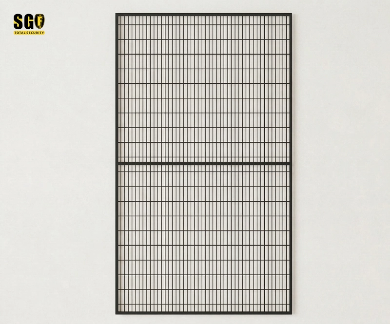
Only the narrow dimension of an opening is read against the reach-through table. A 20 mm wide slot admits the fingertip and stops before the first joint, so there is nothing to hook a finger behind and no grip to pull a hand towards a nip point. Run that 20 mm down the table and 120 mm is the permitted offset — a number you can put in a signature block next to a drawing number. The 100 mm length is what buys the sight line: the operator can watch the tool, chip and coolant stay in the cell, and the panel still behaves like a physical guarding solution rather than a solid wall. Wire diameters of 3.0 mm and 4.0 mm in a Q235 carbon steel frame keep the open area and the stiffness in the same panel.
A stable panel geometry is what keeps the number valid
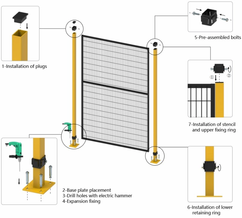
An offset is only true for the opening as built. Posts are 60 x 60 mm square tube at 2.0 mm wall, base plates are anchored with expansion bolts into the slab, and every mesh panel is captured top and bottom by fixing rings instead of hanging from one clamp. Flat full weld with the bead dressed flat matters here for a second reason: the slot band has no burr for a glove or a wrist to catch on. A post that leans, or a frame that deflects under a pallet truck nudge, opens a 20 mm slot into a hand-sized gap — and the 120 mm you signed is no longer the distance in front of the hazard. That is the failure mode that hides until commissioning.
Finger-safe mesh does not cancel the height and reach-over checks
A 20 x 100 mm aperture answers exactly one question: reach through. It says nothing about reach over the top of the guard, reach around the end of a run, or reach through a hinged safety door. Those depend on how high the hazard sits above the floor and on the posture the task forces, which is why standard heights of 2000 mm and 2200 mm are a starting point and not a specification. A cell with a low nip point on a conveyor is a different conversation from one with a spindle at chest height, and the gate opening needs its own distance plus its own interlock. Where forklift or AGV traffic shares the aisle, panel impact resistance — rated at 1600J on these panels — belongs in the same review, because a deformed panel changes the geometry that the distance was calculated from.
Where a 120 mm floor changes the plan
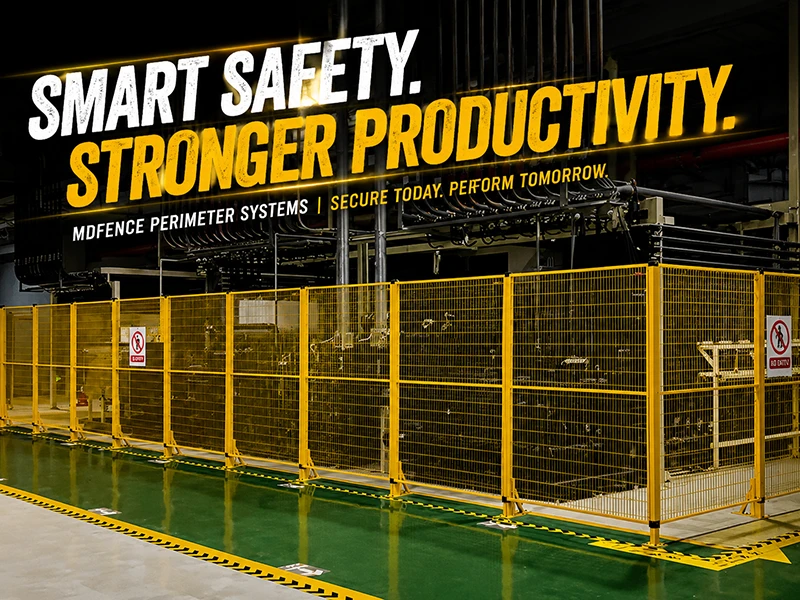
- Robot cell guarding on a line where the difference between 120 mm and a metre decides whether the second cell fits in the aisle.
- Automation system isolation and equipment isolation in cells that were already laid out before guarding was added.
- CNC machine guards and machine perimeter guarding, where an operator still needs to see the tool through the panel.
- Conveyor line safety guarding and palletizer safety guarding with low nip points that drive the height check, not the mesh check.
- Press shop safety fence and welding shop safety cells, where the interlock door is the real boundary of the protected area.
- Warehouse rack protection and smart warehouse zoning, where a modular safety barrier has to be reconfigurable rather than cut and re-welded.
Achieving equipment safety isolation in limited space is mostly an arithmetic exercise done early, with the opening, the body part and the distance written in that order. Compared with welded safety fencing, a modular frame keeps that arithmetic editable: move a run, add a panel, and the documented opening stays the same, so the distance does not have to be re-derived from scratch. This is the practical side of the modular vs welded safety fencing decision — not installation speed alone, but whether the safety distance survives the next layout change.
CAD first: model, drawing-based module list, distance worksheet
Send the cell drawing or a marked-up photo of the equipment. You get the STEP and DWG models for posts, mesh panels, gates and base plates; a bill of materials generated from the drawing rather than typed by hand, with post count, panel modules, gate kits and anchor quantities; and the reach-through distance that the chosen opening supports, listed per run. Dropped into CAD before steel is ordered, that package shows the interference with conveyors, cable trays and door swing while it is still a modelling problem — which is the point where engineering hours are cheap and layout changes cost nothing on site.
Send the layout, get the fence line back
Share the drawing with the hazard locations marked. We return the panel choice with its opening width, the ISO 13857 safety distance that opening supports, the height that closes the reach-over path above your hazard, and a numbered module list for the CAD check — so the number you sign is one you can defend at commissioning.